
By Roddy Scott Follow
More by the author: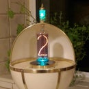

About: I learned to take things apart before I could put them together. Reasonably handy with a screwdriver. Can count to twenty without taking my socks off. Learned a lot of things that are of no use at all. H8 txt … More About Roddy Scott »
In February 2015 I built a massive Steampunk Lamp with an IN-12A Nixie Tube Clock for my daughter's birthday (photograph in Electronics section and now an Instructable!) and since then I wanted to make another Nixie clock but in a totally different style.
I wanted to use end view Nixie Tubes again but this time bigger so I got a hold of some IN-1 NOS (new old stock) Nixie tubes.
What type of clock? After several designs ended up in the waste paper bin I came up with the idea of suspended digits over a wooden base and the first few ideas that I had were just not all that great looking so it was back to the drawing board, again!
I settled on the design you see here and wanted to use some white oak that I had for the parts. A trip to a scrap yard a couple of years ago to get parts for my car resulted in finding a couple of samples of white oak bannister and 4 spindles in the boot of one of the cars. These lay in my shed gathering dust until I began this project.
White oak is a very hard wood as I found out, cutting off the square sections of the spindle on my ancient mitre saw was not too bad but cutting the bannister sample to length I thought my arm was going to fall off!
I started on the part for the tube holders first by mounting the square section in my small metal lathe with a set of reverse jaws and a home made live spindle to stop it flying off. I turned it down from the square section to the maximum diameter that I could get from it, 47mm. Then it was back to the mitre saw to cut the sections to rough size.
The first one I mounted in the lathe and drilled through with the largest drill I had before using a boring tool to enlarge the hole diameter to that of the glass envelope of the Nixie tube. I reversed the section in the lathe and set the depth of the boring tool to leave an internal shoulder that would let the Nixie tube glass protrude just enough for the display.
Doing it this way was time consuming so I then marked the centre of the other three sections and used a 25mm Forstner bit in my milling machine and hand held them as I drilled the whole way through.
Not to be recommended as the oak shavings come out very hot!
Then the holes were completed to the required internal diameters on the lathe with the boring tool. Once this was done I then set up a stop on the bed of the milling machine so I could position the sections above one of the slots. I centered the head to the slot and with a succession of drills, drilled out the first set of holes to 8mm. Moving the bed to set the distance between the hole I then did the same sequence for the second hole, ensuring that it was parallel to the first.
The next step was to round off the tube end of the Nixie holder with a router rounding off cutter in the milling machine.(no photos of this as I forgot to take them!)
As I said, cutting the bannister section was hard going but the following tasks were a bit easier. Unfortunately I forgot to take more photographs of the steps involved but a verbal description should give you the idea.
I was going to keep the top curve of the bannister section but decided to take it off with an end mill on the milling machine to leave a flat surface which had the edges nicely rounded off with the existing shape of the section. Turning it over and clamping it on top of some thin plywood to protect the top I marked out and cut the recess for the electronics into the base as you can see in the photograph.
The next step was to get the holes for the copper tubing drilled from the ends to the recess. This was an exercise in ingenuity itself! My millling machine does not go high enough to use for this, my cheap benchtop pedestal drill does not have enough of a gap between the head and base plate and hand drilling was out of the question as accuracy was needed! How am I going to do this?
Sitting staring at the drill I remembered that when I assembled it, the whole head assembly had to be mounted on the support pillar and that it could be slackened off and rotated away from the base, I did this only to find that I still did not have enough height! I took the securing bolts out of the bench and raised the whole drill up on 40mm of MDF and clamped it to the bench. Height sorted! I had to secure the base section so I clamped that to a heavy machine block and set it up for being 90 degrees to the drill base and then drilled both ends of the wooden base section for the copper tubing.
To get the ends curved I first trimmed off the excess with a saw and then made two holes in the base to accept a 10mm steel pin. I had a piece of 20mm aluminium plate in which I also made a 10mm hole. This was clamped down to the bed of the machine when the drill was still in the hole to get a dead centre point for forming the end curves.
Replacing the 10mm drill with a 12mm milling cutter I move the bed away from it and fitted the oak base to the aluminium plate. With the cutter running and the wood angled away from it I slowly brought it into contact with the cutter by rotating it about the pin and formed the curves in several careful passes as there is a tendency to splinter the rear of the curve as the cutter is always turning into it.
I originally wanted to use 10mm copper tubing but the local DIY superstore did not have any in stock and I wasn't going to go traipsing about looking for 10mm so I bought the 8mm tubing that they had there. Luckily, the 8mm proved to be more pleasing looking that 10mm would have been.
How to bend copper tubing and fail first time around!
I made a round disc of MDF and created a groove in it to accept the tubing - Great!
I cut a section of the tubing and then proceeded to bend it around the disc. When I removed it, the tubing had flattened out in the bend and was more oval than round - FAIL!
I knew that to bend copper tubing you really need a former that holds the tubing against the disk to shape it as you bend it or you need a bending spring that you put inside of the tubing before bending it. I had neither and then I remembered that in an RC Forum that I belong to that one of the guys was bending aluminium tubing and getting the same results as I have here until another member told him to pack it with sand first.
8mm tubing does not lend itself to being packed with builders sand! What next? Fine grain sand? Then the light bulb appeared above my head, SALT!
Less than a Euro later and I was bending the tubing like a Jedi Master! I had sealed one end with duct tape and then filled the tube with the salt making sure that it was packed as tightly as possible by tamping down with the end of a tight fitting drill and then covered it with duct tape too.
I formed all 4 of the curved sections and adjusted each until I had a matching set of 4 curves and then trimmed to length with a dinky little tubing cutter I use for plastic tubing.
I set out the holders and cut 6 short pieces for the interconnecting sections, removed all of the internal burrs with a round file and emery paper. When you uncoil this type of tubing it is very hard to get straight so I put the shank of a close fitting drill in the short sections and rolled them between two thick plates of MDF to get them a bit straighter.
Time to dry assemble the parts!
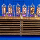
Pushing the short sections into the tube holders first and spacing them equally I fitted one set of curves to the base, so far so good. With a bit of effort I fitted the other set of curves and made adjustments for alignment of the tubes to the base. The resulting look was exactly what I had hoped to achieve.
White oak when raw has a nice grain and figure to it and this is enhanced with finishing, the better the finish, the better that the wood shows its figure.
I was not wanting to stain the oak nor was I just going to varnish it as this detracts from the natural look. When wood is first cut it has moisture in it and the drying process changes how it looks, trying to get this look back is best done with oils.
The first task was to get all of the parts as smooth as possible and try and remove any imperfections from the construction of them. The tube holders were easily done in the lathe but the base section still had varnish on most of it but this was removed by working up from medium to extra fine grit aluminium oxide sand papers and finishing with a very fine Scotch Brite pad by sanding with the grain.
There are many finishing oils on the market and one that lends itself well to white oak is Danish Oil. The one shown in the photograph is a good enough version and is very easy to use as per the instructions on the can. The only issue is that the wood feels tacky and damp after applying but there is a cure for this. Apply the oil to the wood as per the instructions and allow to soak in / dry for at least 24 hours.
Once dry gently rub the wood along the grain with an extremely fine sand paper / emery paper to even it out. I used 800 then 1400 grit emery paper for this step.
The Cure.
Mix equal amounts of Danish Oil, White Spirit and a proper varnish! Do NOT use polyurethane based varnishes as these will not mix with the oil and white spirit, use a varnish such as Yacht Varnish and apply with a soft brush in the direction of the grain and make sure that the end grain is well covered. This combination will get pulled into the pre-oiled wood as the white spirit acts as a solvent carrier and draw the solution into the wood. Allow to dry for at least 48 hours and rub down again with the finest of abrasive papers again. This takes out any raised imperfections. Apply another coating of the mixture to the wood and this should then start to give a depth to the look of the grain. Allow this to dry completely and rub down again if required. If you want you can finish with a thin coat of varnish (thin it down with white spirit), I used satin finish as I did not want it to be too shiny in comparison to the glass of the Nixie tubes.
Put aside to a safe place to avoid damage and let dry thoroughly.
Polishing the copper is the easy part and there are many brands of polish on the market. I tested those that I had on a couple of offcuts of the tubing and the best result came from an Aluminium Polish followed by a polish with Brasso liquid. The aluminium polish has very fine abrasive particles and mine is so old now that it has become a paste which works well, the Brasso just gives that extra depth to the shine afterward and removes any fine scratching from the paste. Wipe down and polish with a soft cloth before coating with a protective coating of clear polyurethane spray. I just knocked some small panel pins into a bit of MDF to support the parts as I sprayed them.
Spray the parts in a warm environment as if it is cold the polyurethane spray will be milky and do not get too enthusiastic with the spraying, several light coats are better than one heavy one - ask me how I know this!
When I built the Steampunk clock for my daughter I used a FunKlock kit from PV Electronics with IN-12A Nixie tubes. I was going to use the same tubes again but I wanted to have round displays of the numerals this time as the IN-12A are rounded oblongs so I contacted Pete, the owner of PV Electronics, to find out if the same kit was capable of powering the IN-1 Nixie tubes. As it happens, it can with no need to alter the kit.
Dealing with PV Electronics is simplified with the online live chat and Pete is only too willing to offer advice and sources for parts he does not carry. He put me on to an Ebayer who sells crimp push on connections that are suitable for using with the IN-1 Nixie tube base pins. Pete's customer service is second to none and I would recommend his kits for projects such as this.
Building a PV FunKlock is an easy exercise if you can identify components, solder and use a pair of small wire cutters with confidence. The kit is designed in two parts - the main controller and the tube board, these connect together with board headers to form a compact unit. The downloadable instructions from PV Electronics are excellent and it is just a case of following them to the letter for a problem free build.
The images of the two boards show how compact this clock module is. Even with its case and with the IN-12A Nixies it is a very small unit. In the other image the LEDs are on the left and the AM/PM Neons to the right
As I was not mounting the Nixie tubes directly to the tube board but using remote wiring instead I had to make a direct connection to one of the tube bases on the tube circuit board as well as the 4 Anodes. As you can see, the pins are easily identified on the IN-1 tubes and with a multimeter I was able to confirm the positions of the cathodes of the tube base to the circuit board.
I created enough depth in the recess of the base in order to contain the wiring from the Nixie tube section along with the circuit boards. It will also allow the installation of the SET and ADJ switches which I removed from the main board and will be activated from the rear of the base unit.
Once the Nixie tubes are in place and secured connecting the Nixie tubes up is done by the use of Molex type sockets which are covered by heatshrink. It is a slow task making up the wiring as it has to be installed to the Nixie Tube holders in sections as each tube holder is linked to the adjacent one and you cannot get all of the wires through with the connections in place. Note:- I used 22AWG wire for this project.
I cut all of the wires required to length and fitted the connection sockets to a pair of wires for each pin. Heat shrink covered the exposed ends and they were numbered for connection to the pins on the Nixie tubes. The sockets are connected to the pins and the free ends of the wires are fed through the tubes on either side and then the sockets are fitted, heat shrunk and numbered before connecting to the next Nixie tube.
The LHS connecting copper tube only has 11 wires coming from it, the next one has 12, the next one has 13 wires in it and finally, the RHS copper tube that feeds down to the circuit boards has only 14 wires (4 Anodes & 10 Cathodes) due to daisy chainng the cathodes and utilising the PV Electronics multipexing circuit. It is just a case of starting from one tube and connecting the wires to the selected pins of each Nixie tube then feed down to the tube board. The 10 cathode wires that come down the copper tube to the recess are then soldered to one of the existing Nixie tube connection pad sections.
The Anode wires are then connected to the relevant opto isolator for each Nixie tube. Easy as pie!
On power up I found that several of the digits in the Nixie tubes did not scroll through as they should have done. I checked the circuit boards for any defect but found none so it was down to a wiring issue.
Testing out the wiring I located several open circuits that were caused by the insulation crimp part of the connectors severing the conductor of the wire. Pull off every connector and test for opens - ARGH!
Several hours later.
I had to remake 5 of the connections and as I installed the wiring this time I tested the continuity for every section. Powering up I found that one of the 'tested' Nixie tubes was faulty. Tube tester purchase on the wish list.now!
After replacing the faulty tube the clock powered up and gave a satisfying red glow and I set the parameters I wanted for the display. This is covered very well in the FunKlock assembly instructions.
Finally Clock No.2 is complete and working!
Remember those 10mm holes I made for forming the end curves? They came in handy for mounting the Set & Adjust buttons as I wanted to remove them from the circuit board along with the power inlet. Some hot glue secures them to the base and the power inlet to the rear of the base making for a tidy installation.
I will be fitting orange/red LEDs to the circuit board and a diffuser plate to give a glow emanating from the underside of the base. Did this but a poor photo of the effect, folks! I used brass dome nuts to make the feet to allow the glow out.
Despite all of the little setbacks this has been an enjoyable build and the end result is worth the effort.
Resources
PV Electronics for the FunKlock kit.
EBay for the IN-1 Nixie tubes
EBay for the 22 AWG connecting wire
Ebay for the crimp connectors
B&Q for the 8mm copper tubing
Scrap yard for the white oak parts!
Tools
Hobby lathe, Milling machine, Pedestal drill, Soldering Iron, Electronic snips, Hot glue gun, Screwdrivers, Craft knife, Drills, Forstner bit
Danish oil, White spirit, Yacht varnish, Sandpaper,